FISS Control Program Manual (v 1.1)
Writer: Juhyung Kang
Original Markdwon File download: obs_guide.md
PDF File Download: obs_guide.pdf
1. Program Information
The currently available FISS control software is written in Python, unlike the previous one written in CVI.
The program is compatible with the Python verison 3.6 or higher, and some of the progroam tools previously written in CVI are loaded in to the dynamic link library (dll). Camera control tool is in CCD.dll, grating and camera focus control tool is in gratfocus.dll and scanner control with observation mode control is in scanobs.dll. Main interface such as GUI program is developed with the PyQt5 pacakge in Python, and 4 to 5 threads will be run until observation. The initial version of the program was successfully debugged at July 20, 2020. This inital version was written by the one of the solar group member in Seoul National University, Juhyung Kang.
The FISS control program is mannaged with the GitHub and, that program is located in the "C:\Control_Program\fiss_control\new" directory in the BBSO local descktop. Please contact with the software manager (Heesu Yang or Juhyung Kang) when you modify the control program.
2. Initialization and Observation
Step 1
Remove the cover (Grating/ Scanner)
Step 2
Turn on the FISS control box and computer in server room (connet to the desktop with the chrome remote desktop, Teamviewer or VNC)
Step 3
Execute the FISS program link file located in the desktop (
Step 4
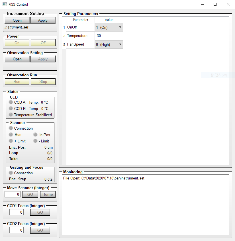
Check the temperature parameter of the CCD in Setting Parameter tab and then click the "Apply" button in Instrument Setting tab.
Step 5
Click the On button in Power tab to turn on the FISS (The FISS is successfully turned on if the CCD, Scanner and Grating and Focus connection lights are turned on after 5 to 10 seconds.) Since the cammera cooling process takes about 30 minutes until cooling at -30 degree celsius, please click the power on button before start to align the optics.
Step 6
Check the FISS slit cover is opened in Coode room.
Step 7
Check the alignment in FISS instrument. Check the incident light enters vertically as you screen the light with the paper gradually (The light should be enters to the top inside the FISS instrument) and also the incident light goes to grating (Please contact with the BBSO in advance when you use FISS because the most of case use VIS instrument before).
Step 8
Change the filters with wavelength bands to be observed
- Set 1 - CamA: H 6563 Å / CamB: Ca II 8542 Å
- Set 2 - CamA: Na I D2 5890 Å / CamB: Fe I 5434 Å
Replace the filter in front of the CCD. Filter is in the FISS toolbox. The glass surface is outside the CCD, and the mirror surface face to the insde.
Step 9
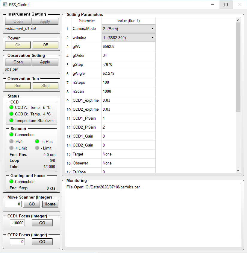
After the CCD temperature is stabilized, click the open button to open the observatioal parameter file (.par) in the Observation setting tab. Following figure shows the FISS program after open the parameter file. You can lean how to write the parameter file in 3. Setting Observation Parameter section.
Step 10
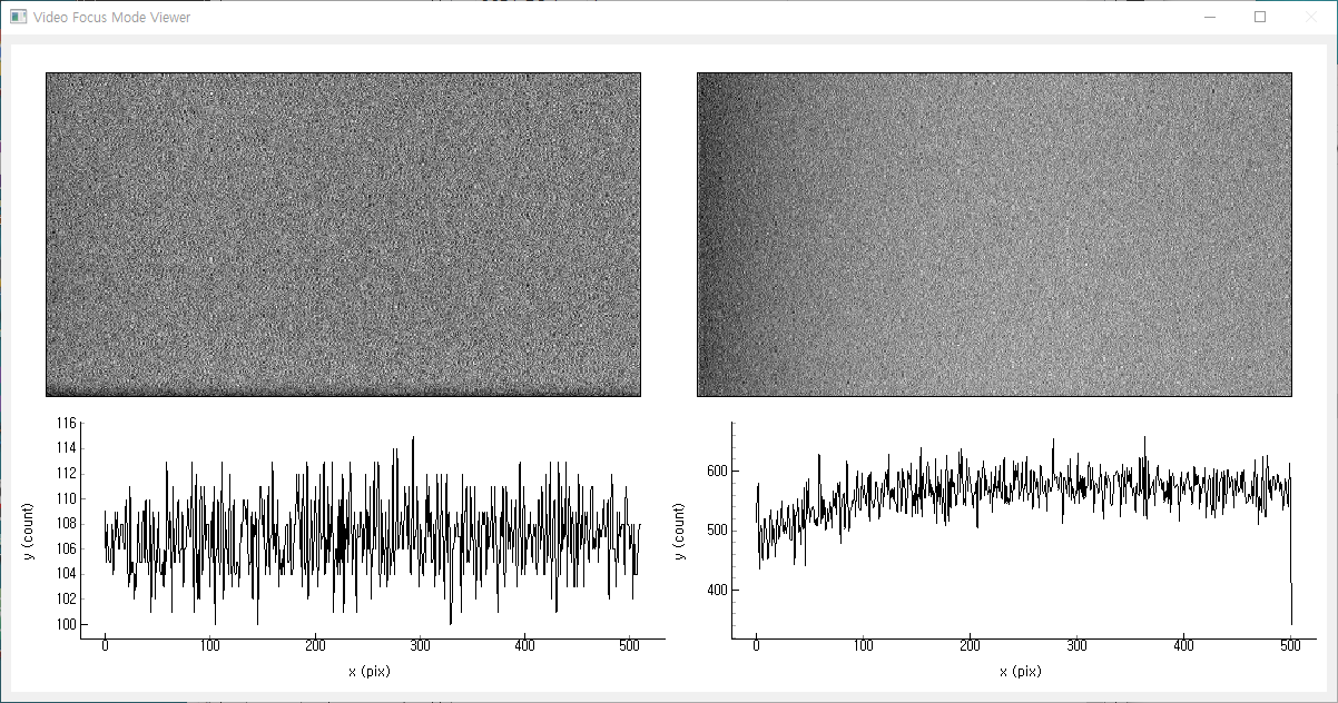
Focusing. Screen the some portion of slit and check wheter the boundary is clear in display. The second way is to check wheter the brightness in slit (y) direction varies ahrply in spectrogram. (It is quite useful to run the video focus mode to check the spectrogram and line profile simultaneously. Set the AcqMode equal to 0 (video mode) and then click the Apply button in Obseravtion Setting tab then click the run button in Observation Run tab.)
When the Video mode, the video image viewer windows is popped up as like the following figure.
Step 11
Take Flat image. We recommand to take a flat image at least 2 (before and after the observation) and also take the flat if you changed the filter set. When you take the flat image, please require the operator then operator move the telescope to the Disk center without AO. Set the AcqMode equal to 10 (Take Flat). If modify this parameter click the Apply button and then click the Run botton. The flat image will be saved in C:\Data\YYYY\MM\DD\cal directory.
Step 12
Set the observational parameters. You can use the paramter files directly also modify the parameters in the Setting Parameter table (Please see the 3. Setting Observation Parameter section if you are not familiar with this). You can check the general observational parameters is in sample_files.zip. We highly recommand that double check the PGain, Gain and exptime parameters before run observation. The common settinf parameters for each filter sets are shown in following table.
| Filter Set | Set1 - A: H / B: Ca II | Set2 - A: Na I D2 / B: Fe I |
|---|---|---|
| wvIndex[1] | 1 | 2 |
| PGain | A: 2 / B: 2 | A: 2 / B: 1 or 0 |
| Exp. Time (ms) | A: 30 / B: 30 | A: 30 / B: 10 |
Step 13
After modifing the parameters, click the Apply then the temporary applied parameter will be saved at "applied.par" file in C:\Data\YYYY\MM\DD\par directory. After clicked the Apply button, the Run button will be enabled. Then click the run button to run observation. If you stop the observation click the Stop button.
Step 13-1
Before starting the observation loop, you have to check that the target of observation is located at the center of FOV. To check this, we recommand that Scan the large FOV at first and move the scanner. At this sequence you set the nScan equal to 1 to take only one raster image. If scan is done, insert the value to move scanner in Move Scanner tab then click the Go button. After reach the scanner at that position click the Home button to set this point to the zero (home) position. Repeat this sequence after reduce the FOV to the observed size until the target will be located in the correct position.
Step 13-2
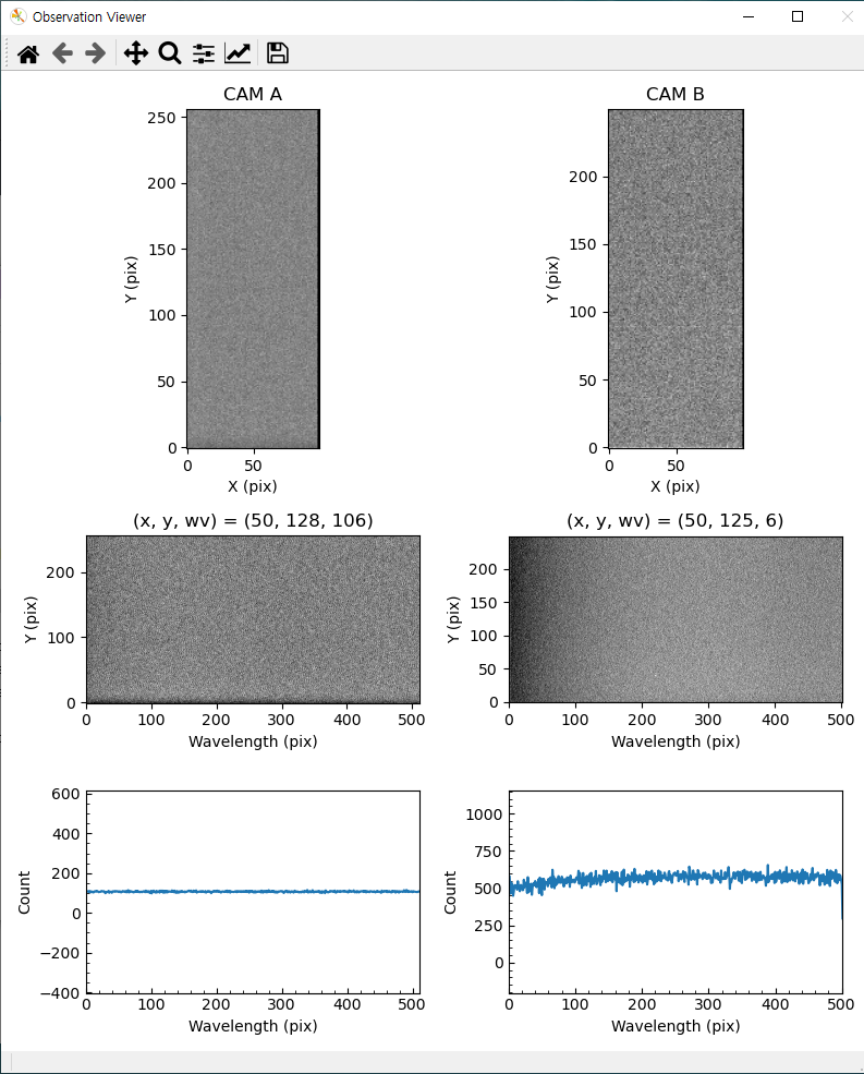
Set the observational parmeter to fit the your observation loop. It is the good way to set the nScan value to the high value and then stop the observation to run observation continuously. Again, the one of the most important parameters is Target since that parameter is the directory name of the observed data. Please set this value to fit the each observation target. The observed data will be saved in C:\Data\YYYY\MM\DD\raw\ {Target} directory. The data filename is scan start time for example FISS_YYYYMMDD_HHMMSS.SSS_A.fts. The datails of the parameters and the cadence for each number of nSteps is in 3. Setting Observation Parameter
When you run observation the image viewer will be popped up like follows:
Step 14
Take a Flat imgae after final observation end.
Step 15
Turn off the power by click the Power Off button. When you click Power Off button, the program will be closed automatically after heating the CCD at 5 degree celsius. Since It takes a lot of time, we recommand to cover the grating and scanner during the heating time.
Step 16
Download the observed data on your portable hard driver. If control program is turned off, than power off the control box except for the desktop and go to lodge (you download the data remotely).
3. Setting Observation Parameter
Unlike the previous control program, the new program use the parameter file (.par). You can download the (sample_files.zip). Check these files to learn how to write the parameter file. You can also download the program which generate the parameter files (mk_obspar.exe). You can also modify the parameter in FISS control program, but you can not define the number of observation loops (nRun). The number of observation loops is only set or modified in parameter file by set the nRun value or in the parameter generating program.
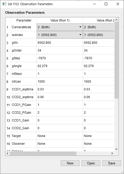
The following figures show an example parameter file and the parameter generator.
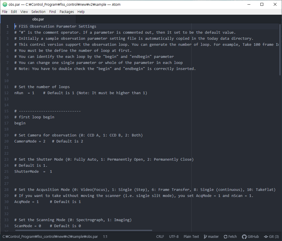
Each observation loops is distinguished by "begin" and "endbegin". For the first loop, you have to define all parameters, but for the following loop, you just define the parameters to be modified. You can check what I mean in the example_nloop.par file from the (sample_files.zip).
Observational parameters in .par file are follows:
- nRun: The number of observation loop.
- CameraMode: Set the camera to be used, Default is 2 (both).
- wvIndex: Set the wavelength band to observe. 1 means Set1 (A: H / B: Ca II 8542 Å) and 2 means Set2 (A: Na I D2 5890 Å / B: Fe I 5434 Å). If you want to set the grating angle manually, set this value as 0 and should set the gWv, gOrder, gStep and gAngle.
- nSteps: is the number of step to take frame (nFrame). In case of nStep equal to 1, the scanner is stopped at origin.
- nScan: The number of repeat to scan.
- CCD1_exptime: exposure time of the CCD camera in second.
- CCD1_PGain: Set PGain Value. Default is 2. Refer to table in Step 12. (0 - 2, integer)
- CCD1_Gain: Set Gain Value. (0 - 255, integer)
- Target: Target name. We recommand to change this when you change target.
- Observer: Name of observer.
- TelXpos: Position of the pointing of the telescope.
- stepSize: Step size to move scanner in um.
- HBin: Horizontal (spectral direction) Binning.
- VBin: Vertical (slit direction) Binning.
- AcqMode: Acqusition Mode. In general observation, this value is 1 (Single Step). 0: Video Focus / 1: Single Step / 5: Scan Stop / 6: Frame Transfer / 8: Scan Continuous / 10: Take Flat. Among these value, you can use 0, 1 and 10, 5 and 8 will be deleted, and 6 will be added.
- ScanMode: Mode of scanning. Currently 0 is only available value.
- Trigger: Camera trigger metnod. Default is 0 (internal) and external trigger will be added soon
- ReadMode: Camera redout method . 1: full vertical binning, 4: imaging. In general observation, use 4.
- ShutterMode: Camera shutter open/close. In general observation, use 1: open. 0: auto, 1: open, 2: close
4. Cadence
The cadences of the FISS for each number of steps are follows (that comes from the test observation in 2020):
exptime: 30 ms / 30 ms
100 steps (frames, 16 arcsec): 13.4 sec
125 steps (frames, 20 arcsec): 16.1 sec
150 steps (frames, 24 arcsec): 18.8 sec
200 steps (frames, 32 arcsec): 24.1 sec
Set to the pre-setting grating angle (gAngle), wavelength (gWv) and diffraction order (gOrder) values corresponding to grating motor step (gStep). If you set this parameter to 0, you have to set the gWv, gOrder, gStep, gAngle parameters manually. The gStep is the step count of the motor. ↩︎