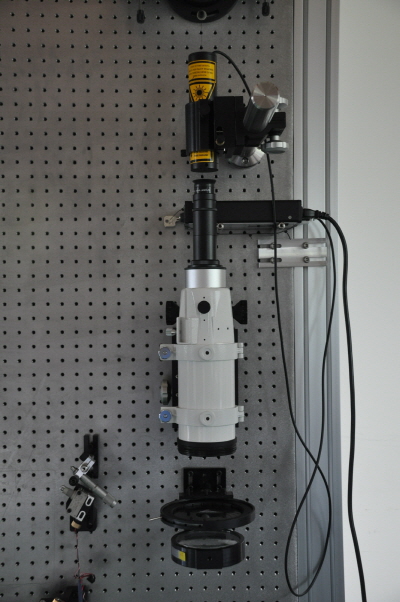
Instrument
FISS
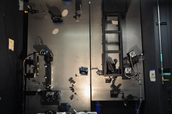
This shows configuration and lightpath in the FISS. As you can see, FISS consist of field scanner, entrance slit, collimator/imager mirror, Echelle grating, bandpass filter and two CCD cameras. We applied Littrow mounting to FISS layout. Littrow mounting leads us to simplify the instrument configuration and compact the size. By using field scanner, we can move solar image on slit surface in left-right direction, and then we can obtain the data including not only spectral information but also spatial information, imaging spectroscopy data.
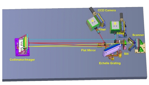
The order of optical ray is as follows:
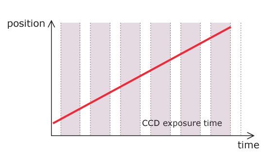
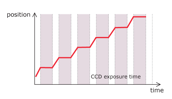
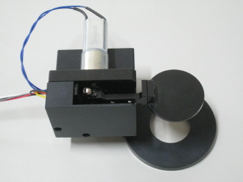
On the contrary to other imaging spectrograph devices, FISS uses a field scanner which is composed of two flat mirrors and a linear stage motor as the movement device. This doesn't require the position of a pupil, and hence it makes the optical design of the instrument more simple. The field scanner uses JSMD linear motor by Justek and PMAC PCI LITE board by Delta Tau. The motion of field scanner divides into two types: step-by-step and linear drift motion. Scanner drifts fast without stop in imaging mode, while it moves step by step in spectrograph mode. The moving accuracy is less 1 μm when the scanner moves 16μm per a step.
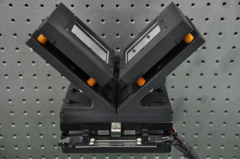
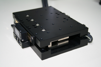
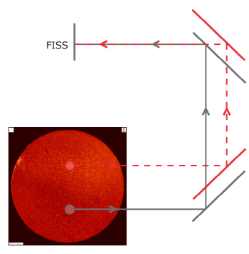
Figure Shows the optical layout of two-mirrored field scanner. The incoming Sun light is reflected by two flat mirrors (bold lines on the right), so that a selected field is incident to the slit. The incoming field can be changed by shifting the location of the flat mirrors. Black arrow is a beam path of a selected field for a mirror location. Red arrow is a beam path of a different field as the mirrors move to a different position.
The slit was designed and made by KASI. The initial design of the slit width was 16μm(0.08") that corresponds to a pixel size of CCD(16μm), necessary to achieve the intended spatial resolution of 0.16". Since the light level was too low to sufficient, the slit width was changed from 16um to 32um. The slit is now attached on the vertical table with its plane facing up. This causes dusts on the slit surface. In order to block dusts, a slit cap was installed in addition.
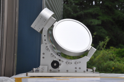
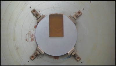
FISS uses an off-axis mirror which originates from a portion of paraboloid mirror. The mirror makes the spectrograph configuration so simple. Also it leads us to avoid chromatic aberration which occurrs in a lens-based optical system. The mirror mount can control its position in 3 axes. The mirror is made of zerodur and is coated by enhanced aluminum. It has a radius of 300mm.
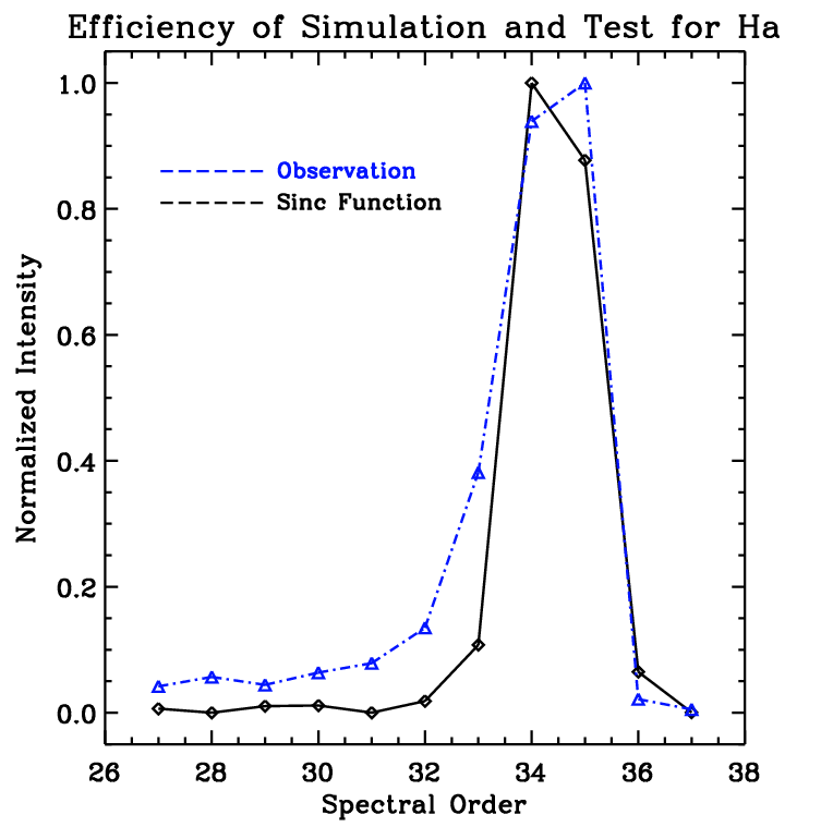
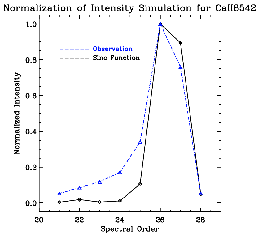
The disperser is the most important component in all spectrographs. Usually prism or diffraction grating is used as a disperser. We have used a Echelle grating. Echelle grating is a kind of diffraction grating. It has low groove density, high blaze angle and wide spectral range. The Echelle gratinig we used is 79grooves/mm, blaze angle of 63.4 degree. The grating surface is coated by aluminum and is overcoated by a thin layer of magnesium fluoride (MgF2) to prevent the oxidation of the aluminum. We use high-spectral order when we observe the Sun : 34th for Hα and 26th for Ca II 8542Å. The grating is mounted on a rotating motor which is controlled by a computer. It enables the grating to fix at or to rotate specific angle during observation. The angular resolution of grating motor is 1.98"/step, which corresponds to about 1 pixel (16μm) on CCD chip.
Same with the previous colimator.
An important limitation of the Echelle grating is order-overlap at high spectral orders. To avoid this order-overlap, we use bandpass filters. Free Spectral Range (FSR) is defined as a criterion of order superposition. It is the largest wavelength range not to overlap with the spectral range in an adjacent order. If the (m + 1)th order of the wavelength (λ) and mth order of (λ + δλ) lie at same angle, FSR is expressed as (λ/m). For example, if we use Hα wavelength and order of 34th, the FSR is about 193Å. The higher the spectral order is, the lower FSR is. If we use the filter whose bandpass is smaller than FSR, we can filter the specific order that we want. For Hα, we used bandpass filter whose FWHM is 100Å by CVI melles griot. For Ca II 8542Å, FSR is 328Å, and then we use the filter with the FWHM of 250Å by Andover Corporation. Filter transmissions at Hα and Ca II 8542Å are 0.66, 0.65, respectively.
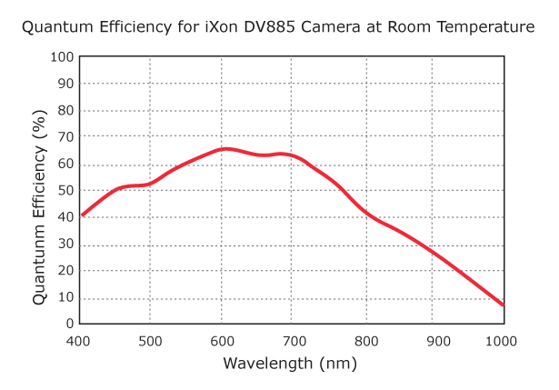
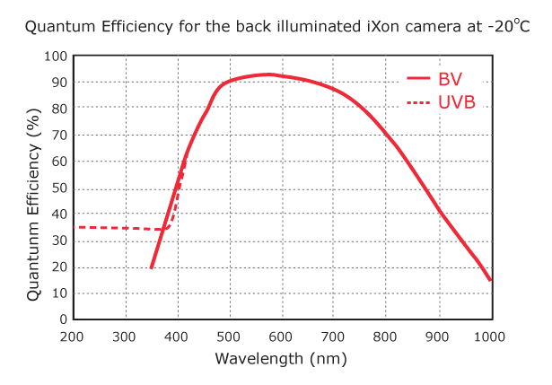
We used two CCD cameras(DV887 at Hα and DV885 at Ca II 8542Å) as detectors by Andor Technology. These are electron-multiplying CCD(EMCCD), which a gain register is placed between the shift register and the output amplifier. The gain register consists of lots of stages, and the electrons are multiplied in each stage, so that it can get thousands of electrons from one electron with low readout noise. The dimension between two cameras are same. Due to anomaly at Ca II 8542Å, a DV887 camera has replaced DV887.
| Specifications | DV887 | DV885 |
|---|---|---|
| CCD Type | back-illuminated | front-illuminated |
| Active Pixels | 512 x 512 | 1,004 x 1,002 |
| Pixel Size [μm] | 16 | 8 |
| Image Area [mm] | 8.2 x 8.2 | 8 x 8 |
| Max Readout Rate [MHz] | 10 | 35 |
| EM Gain | 1 ~ 1,000 | 1 ~ 1,000 |
| Dynamic Range [bit] | 14 | 14 |
Goode Solar Telescope
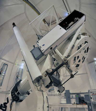
The 1.6m Goode Solar Telescope (GST) is installed in Big Bear Solar Observatory (BBSO) in Big Bear Lake in California. In the ground-based observations, it is the largest telescope in the world. It is used off-axis mirror as the primary mirror to reduce stray light and heat. The spatial resolution of NST is about 0.06 arcsecond at the wavelength of 500nm. If you want to know more information about NST, please visit BBSO website.
Coude Room
We have installed FISS on vertical table in Coude room. Apart from FISS, there are three devices for solar observation - InfraRed Imaging Magnetograph(IRIM), Filtergram at Hα and Adaptive Optics. On horizontal table, IRIM and Filtergram are installed. In case of vertical table, Adaptive Optics (AO) and FISS are installed. The light which is corrected by AO system is used FISS observation.
Software
We have developed the control program for each device using the software development kit (SDK). Each control program is merged as one. After integration of the programs, the program for the observation was developed. Previously, Labwindows/CVI made by National Instruments is used as the software development tool. The new GUI tool has been developed by Python.
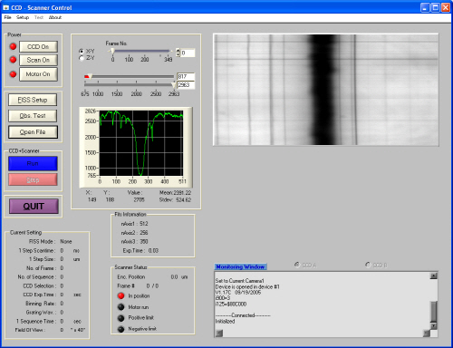
A program technique commonly used in the FISS control programs is the thread. Thread is the smallest unit of processing that can be scheduled by an operating system like MS windows. It generally results from a divergence of a computer program into two or more concurrently running tasks. We used the thread function for the monitoring of CCD temperature, realtime image display, and FISS status display.
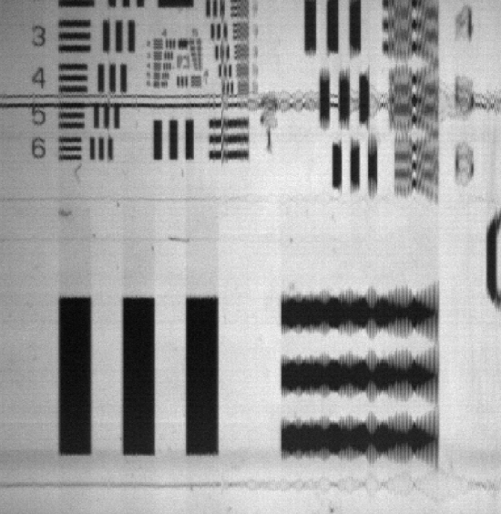
Test Observation